GENERAL
AKON’s model A20-MX208 is a critical part of our line of products which include matching receiver/tuners, fast stepping LO synthesizers, and transmit up converters for use in modern highly integrated EW/ECM systems. These subsystems are designed so that the customer can supply his own DRFM and receiver/signal processor subsystems, leveraging the customer’s internal digital processor, software and DSP capability, and allowing the simple purchase of the required microwave components to complete the ECM system.
It has been AKON’s observation that the majority of receiver/processors and DRFMs operate with RF inputs in the range of 750 MHz to 1250 MHz, 500 MHz instantaneous bandwidth. AKON has designed our line of complementary microwave subsystems to directly interface with these customer designed items.
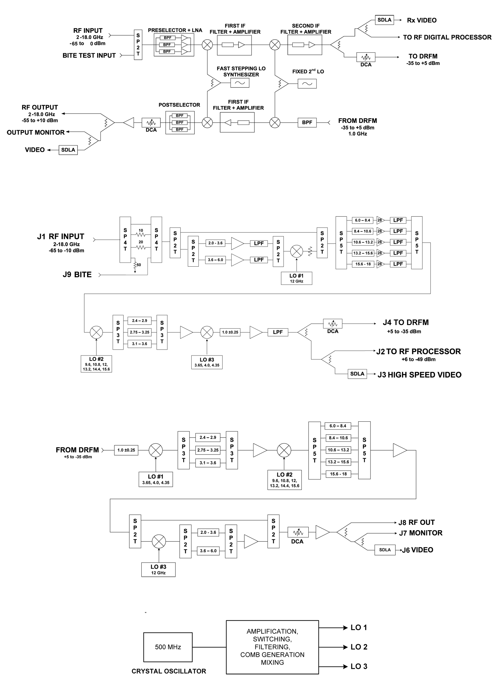
Integrated ECM Converter Subsystem
The Tuner (down converter), Fast Stepping LO and Up Converter work as an integrated subsystem to accept the broadband RF inputs, down convert to a 1 GHz IF for use by the RF Processor and DRFM, and then re-convert the DRFM output back up to the original RF frequency. This is done synchronously by using the same LO source for both up and down conversion processes, and the same IF frequencies in both converters. Both converters incorporate digitally controlled attenuators to compress the input RF dynamic range down to 40 dB for use by the DRFM, and then to proportionally re-expand that range back in the up-converter. Both converters also incorporate high speed SDLAs so the customer has real time information on instantaneous Rx and Tx levels. The up-converter has sufficient output power to drive most HPAs be they either solid state or TWT. See sections below for more detailed descriptions of the individual modules.
AKON Integrated ECM Converter Subsystem
with Synchronous Up/Down Frequency Conversion Block Diagram
TECHNICAL CONSIDERATIONS
2 - 18 GHz Tuner and Upconverter Pair
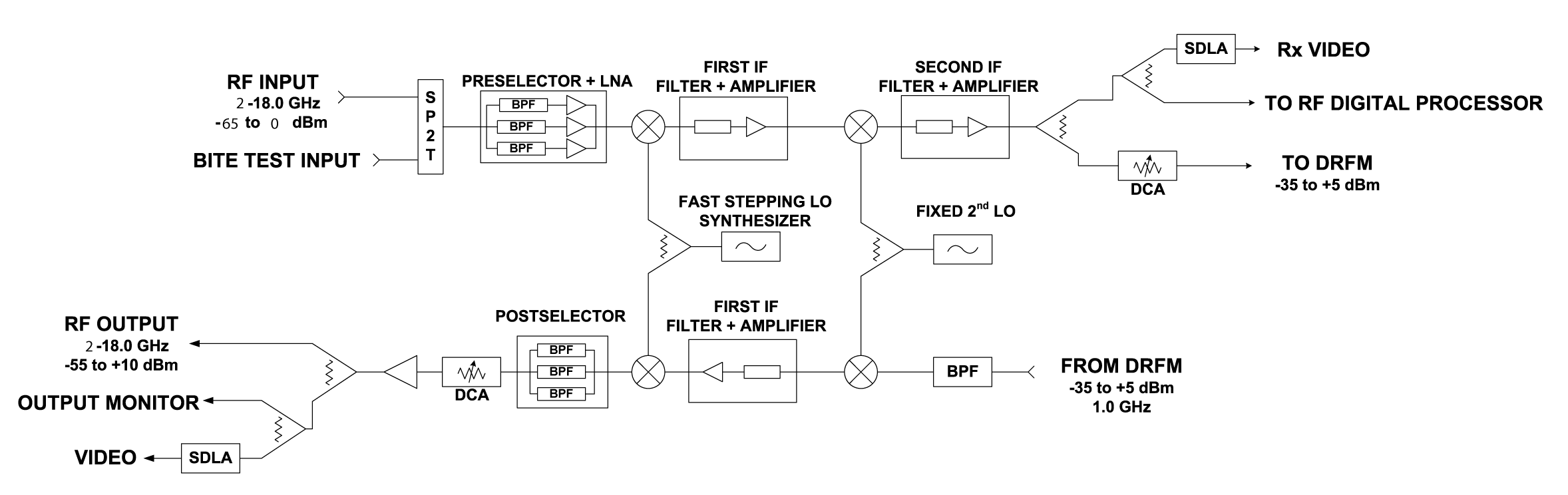
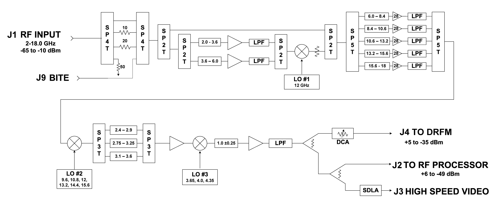
Tuner
This tuner accepts RF input in the range of 2.0 to 18 GHz, and provides a 1 GHz output with 500 MHz instantaneous bandwidth. Tuner architecture is of the “Type-2” variety. This tuner provides 20 dB of gain to the RF Processor port and variable gain to the DRFM port to reduce dynamic range to 40 dB. The noise figure is on the order of 15 dB.
This tuner starts with a pair of SP4T switches which function as both dynamic range expander and BITE input selector. Following that is a SP2T switch which bypasses the 6 to 18 signals around the pre-converter, and sends signals from 2 to 6 GHz to the pre-converter. The pre-converter stage takes the signals in 2 bands, one from 2.0 to 3.6 GHz and 3.6 to 6.0 GHz, mixes them with a 12 GHz LO, which then puts those signals out in the 6.0 to 8.4 and 8.4 to 10.0 bands.
Following the bypass and pre-converter is the main low noise preselector, which divides the 6 to 18 band into five sub-bands of 2400 MHz width each. Architecture is “Type 2” where the individual preselector channels have the LNAs after the sub-octave bandpass filters, which eliminates LNA harmonic spurious from causing false signals in the system.
Following the preselector is the first down conversion mixer, which down converts each preselector band into a first IF band of 2.4 to 3.6 GHz, which is 1200 MHz wide. Following this mixer, this IF band is then further sub-divided into three 500 MHz wide bands with overlap, in a switch-filter bank. Following this filter bank is the first IF amplifier.
Following the amplifier is the second conversion mixer, which mixes the selected first IF sub-band with the proper LO frequency to result in a 1.0 GHz second FI signal with 500 MHz bandwidth. This mixer is followed by the second IF bandpass filter and second IF amplifier. This IF amplifier is followed by a low pass filter to eliminate the amplifier’s harmonic, and then a network of power dividers to provide the various outputs to the Receiver Processor, a high speed SDLA which provides Rx video, and through a DCA to the DRFM. The DCA is used to compress they dynamic range down to 40 dB for the DRFM.
2 - 18 GHz Tuner Block Diagram
| Input Frequency Range (GHz) | 2.0 to 18.0 | |
| Input Dynamic Range (dBm) | -65 to -10 | |
| Max RF input, no damage (dBm) | +20 CW, +50 peak, 1 μs | |
| RF Channels (GHz) | 2.0 - 3.6 | 10.6 - 13.2 |
| 3.6 - 6.0 | 13.2 - 15.6 | |
| 6.0 - 8.4 | 15.6 - 18.0 | |
| 8.4 - 10.6 | ||
| First IF Frequency (GHz) | 2.4 - 3.6 | |
| Second IF Frequency (GHz) | 1.0, 500 MHz 1 dB BW | |
| Second IF Bandwidth (MHz) | 500 (1.0 dB) | |
| Conversion Gain (dB) | 20 | |
| Conversion Gain Adjustment (dB) | 30, 0.5 dB resolution | |
| Noise Figure (dB) | 15 typ, 16 max | |
| LO1 (GHz) | 12 | |
| LO2 (GHz) | 9.0, 10.8, 12, 13.2, 14.4, 15.6 | |
| LO3 (GHz) | 3.65, 4.0, 4.35 | |
| Image Rejection (dB) | 60 | |
| Spurious (dBc) | -60 | |
| DC Power | +12 Built in DC - DC Converter | |
Tuner and Upconverter Pair
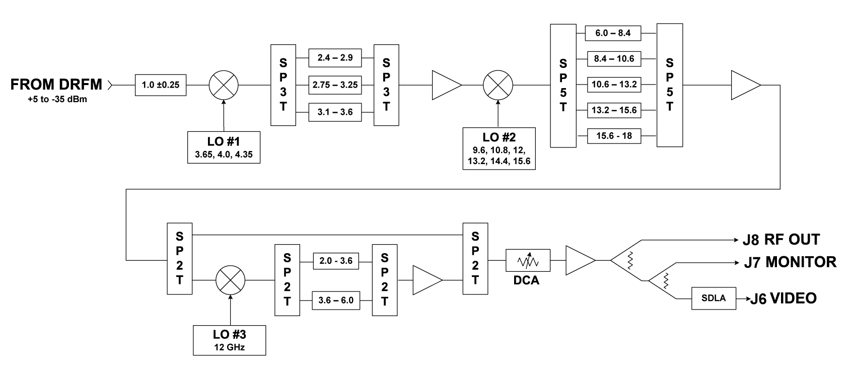
Upconverter
The 1 GHz output signal from the DRFM first passes through a bandwidth limiting and anti-aliasing filter which restricts the operating band to 750 MHz to 1250 MHz. Following this filter the first conversion mixer where the signal is mixed with the same LO as was used in the down converter, to result in a first IF signal in the 2.4 to 3.6 GHz band. A switch filter bank selects one of three 500 MHz wide segments of this band, same as was used for the down conversion. This filter bank is followed by an amplifier to bring the signal back up to a level which is good for mixer drive.
The signal is then mixed in the second mixer, again with the same LO signal as was used in the tuner, to convert the DRFM signal into the corresponding frequency in the 6 to 18 GHz band. The second mixer is followed by another switch filter bank post selector as was used in the Tuner. This filtering eliminates images, harmonics and spurious mixer products. Following this filter bank is an RF amplifier to bring the signal amplitude up to a level suitable for use in the post-converter.
Signals originally received in the 6 to 18 GHz band are bypassed around the post converter. Signals originally in the 2 to 6 GHz band are then routed into the post converter where they are again mixed with the 12 GHz LO, and are converted back to their original frequency. The post converter contains the same filters following the mixer as were used in the Tuner pre-converter, which again will eliminate mixer spurious.
Following the bypass and post converter is a DCA which is used to control overall conversion gain in order to expand the dynamic range from the DRFM’s 40 dB back to 55 dB. After the DCA is the final RF amplifier covering the original 2 to 18 GHz, and can provide up to +15 dBm RF drive to the customer’s HPA for transmission. Following this fuinal amplifier is a network of power splitters which provide the main RF output, a monitor port output, and signal to a high speed SDLA which provides log video output of the actual signal sent to the HPA, so that output amplitude can be monitored and controlled.
2 - 18 GHz Upconverter Block Diagram
| Input Frequency (GHz) | 1.0 | |
| Input Bandwidth (MHz) | 500 | |
| Maximum IF Input (dBm) | +5 | |
| Conversion Gain (max) | 5 | |
| Conversion Gain Adjustment Range (dB) | 15.5 | |
| RF Channels (GHz) | 2.0 - 3.6 | 10.6 - 13.2 |
| 3.6 - 6.0 | 13.2 - 15.6 | |
| 6.0 - 8.4 | 15.6 - 18.0 | |
| 8.4 - 10.6 | ||
| LO1 (GHz) | 3.65, 4.0, 4.35 | |
| LO2 (GHz) | 9.6, 10.8, 12, 13.2, 14.4, 15.6 | |
| LO3 (GHz) | 12 | |
| Spurious (dBc) | -60 typ | |
| Output P-1 (dBm) | +15 | |
| Harmonics (dBc) | -30 | |
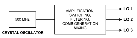
Local Oscillator
The LO assembly for this Tuner and Up-converter pair is relatively simple, in that only nine fixed frequencies are needed. Those frequencies are: 3.65, 4.0, 4.35, 9.6, 10.8, 12.0, 13.2, 14.4 and 15.6 GHz. This assembly consists of a 100 MHz TCXO as the main frequency generating element. This very stable and low noise oscillator drives a comb generator, which is followed by a network of filters, switches, mixers and amplifiers, which generate the required frequencies.
LO Block Diagram
| LO1 (GHz) | 3.65, 4.0, 4.35 |
| LO2 (GHz) | 9.6, 10.8, 12, 13.2, 14.4, 15.6 |
| LO3 (GHz) | 12 |
| Switching Time (ns) | <100 |
| Overall Accuracy (ppm) | +/- 30 |
| Phase Noise (dBc) | -90 @ 1 kHz |
PACKAGING
All three assemblies are similarly packaged in MIL grade environment-proof aluminum enclosures of approximately 8.5” x 6.0” x 2.3”. Wedge locks are on the edges for secure mounting into the equipment rack. RF interconnections are via SMA connectors, DC and control signals are brought in on micro-D connectors. Units are powered from +/- 12 VDC.
OPTIONS
Customized versions of these assemblies are available on a special-order basis, which can have different RF input frequency ranges (including millimeter bands), different conversion gains, different IF (to/from DRFM, RF processor) center frequencies and bandwidths. AKON additionally provides other associated microwave EW assemblies such as Digital Frequency Discriminators, Extended Range High Speed DLVAs, Switch Matrices, Switched Filter Banks, Front End Amplifiers, and ECM. Please contact AKON directly with your specific needs and discuss the options with one of AKON’s EW experts to determine the best solution for your microwave requirements.