This is a general list of terms and relationships commonly used in specifying Detector Log Video Amplifiers (DLVAs), Extended Range Detector Log Video Amplifiers (ERDLVAs), RF Log Amplifiers and Log IF Amplifiers.
Absolute Accuracy:
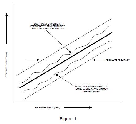
This is a measure of total power uncertainty around a fixed mathematical straight line (defined as a reference line) as the RF frequency, RF power and temperature are varied. The absolute accuracy includes the effects of log linearity, frequency, temperature variation and output D.C. offset variation and is measured in ±dBs. See Figure 1.
C.W. Immunity Dynamic Range:
This defines the C .W. range above "threshold" sensitivity level so that a pulse level at threshold sensitivity level can be measured within a specified error value, while rejecting the C.W. level.
C.W. Rejection Time:
This describes the time required by the device design to cancel the maximum specified C.W. level so that the pulse level at the threshold sensitivity value can be measured within specified error value. Rejection time can be different when C.W. turns “on” and when C.W. turns “off” and needs to be specified for a given device design.
Dynamic Range:
Defined in dBs from T.S.S. to end of logging range. Dynamic range is a very popular term that is generally confused with logging range.
D.C. Output Offset:
This is defined as the output D.C. voltage with no RF signal applied and input RF port terminated into a 50 ohms.
D.C. Output Offset Variation:
This is defined as the output offset voltage variation with no RF signal applied and as the temperature is varied.
Dwell Time (td):
This is defined as the minimum time for the output pulse to be “Flat” within ±X dB for the test condition of minimum required pulse width. It is generally equal to pulse width less settling time (ts). Known also as “Flat Top.”
Fall Time (tf):
This is defined as the time required for the trailing edge of the pulse to fall from 90% value to 10% value for a given RF power level. Generally, the RF level is the highest power level of the “logging range.”
Frequency Flatness:
This is defined as the output voltage variation at a constant temperature and constant RF input power as the RF frequency is varied. It is expressed in ± dBs. See Figure 2.

Incremental Log Slope:
This is defined as slope of the best fit straight line or slope of a defined fixed slope straight line which passes through the actual output voltage data over a limited logging dynamic range, say every 1.0 dB or 2.0 dB.
Log Slope:
This is defined as the slope of the best fit straight line or slope of a defined fixed slope straight line which passes through the actual output voltage data over the entire logging dynamic range. It is expressed in mV/dB ± % mV/dB.
Log Linearity:
Describes the deviation of the actual output voltage from a straight line behavior and is expressed in dBs. Log linearity can be defined in two ways:
Deviation from a straight line whose slope is computed by the least squares method (best fit),
or
Deviation from a straight line whose slope (mV/dB) is fixed. This definition takes on added importance in direction finding systems or any time accurate measurement of the relative power between two signals is required.
Linearity is defined at a given temperature and at a given frequency. See Figure 3.
.jpg)
Logging Dynamic Range or Logging Range:
Defined in decibels (dBs) from usable sensitivity to end of logging range. Essentially indicates the range over which the signal information is processed and exhibits a straight line relationship with defined linearity between RF input power expressed in dBm and linear video output voltage usually expressed in millivolts (mV). See Figure 4.

Partial Recovery Time:
This parameter is critical when two pulse amplitudes need to be measured which are closely time spaced. This is defined as the time required for the output training edge to fall from 1.0 dB below peak to X dB below peak. Commonly, partial recovery is measured for a 16 dB or 20 dB drop in the output training edge voltage.
Propagation Delay:
This is commonly defined as the propagation delay from 50% RF input to 50% video output. However, a more appropriate way of defining the delay time is from 50% RF input to 10% video output as the compression process changes the rise time as a function of power level. Sometimes called delay time. See Figure 5.

Pulse-on-Pulse or Pulse-on-C.W.:
This describes a requirement in the unit whereas pulse amplitude of the signal riding on a C.W. or RF noise level can be accurately measured. Usually, the pulse level can be either weaker or stronger than a specified C.W. or noise level and in both cases needs to be measured accurately.
Recovery Time (trec):
This is defined as the time difference between a threshold sensitivity minimum specified pulse width and a maximum logging range level pulse at the maximum specified pulse width so that the threshold sensitivity pulse can be measured within ±X dB (usually ±1.0 dB) of its value if the high level, wide pulse width would not be present. Generally, recovery time is defined from the 90% point of the falling video pulse to a point of ±1.0 dB of the base line. The DLVA is now “recovered” and able to accept a new RF pulse. Recovery time is sometimes known as Shadow Time because any new pulse occurring during recovery time would be “shadowed.
RF Bandwidth or Frequency Range:
This defines the frequency range over which the specified performance and frequency flatness is achieved. Generally, the bandwidth can exceed the normal frequency range. If a particular band-shape is required, then the amount of rejection at the low and/or high end of the frequency range should be specified. This is particularly important in the case of Log IF Amplifiers. Filtering can be integrated, if necessary.
Rise Time (tr):
This is defined as the time response between 10% to 90% of the video output. See Figure 6.

Settling Time (ts):
This is defined as the time from 10% video output to a time when the video output has settled to ± X dB (commonly ±0.5 dB) of its final steady state value. It is generally 1.5 x rise time tr.
Tangential Signal Sensitivity (T.S.S.):
This is the input RF power level (expressed in dBm) at which the device output exhibits a minimum Signal-to-Noise Ratio (SNR) of 8.0 dB at the specified video bandwidth.
Temperature Variation:
This is defined as the output voltage variation referred to the input power (in dBs) at a given power level and given frequency, as temperature is varied.
Threshold Sensitivity:
Same as usable sensitivity.
Total Response Time:
This is defined as time from 50% RF to when the video output has settled within ± X dB (commonly ±0.5 dB) of its final steady state value. It is usually equal to propagation delay plus settling time.
Trailing Edge Discontinuity Range:
This defines a range in dBs from a given peak value so that trailing edge does not show any perturbation, ringing, change of sign, etc. Usually, this range is from 1.0 dB below peak to 16 dB below peak level, and is critical when pulse width is required to be measured. Usually, discontinuity or perturbation is defined as abnormality wider than 5.0 nanoseconds in width.
Trailing Edge Re -Entrance:
This specification describes and limits the trailing edge under shoot, its positive excursion and ringing behavior during the recovery time. Usually, the positive excursion or ringing of the trailing edge is specified to be below a level equivalent to threshold sensitivity.
Usable or Operational Sensitivity:
The usable or operational sensitivity is generally equivalent to a 14 dB output Signal-to-Noise Ratio (SNR). In general terms, this is approximately 5 dB stronger than the equivalent Tangential Signal Sensitivity (T.S.S.).
Useful Equations and Relationships
Minimum Detectable Signal (M.D.S.):
M.D.S. = 144 + NF + 10logBrBv-Bv2
Where NF = Noise Figure (dB)
Br = RF Bandwidth (MHz)
Bv = Video Band I (MHz)
Also known as maximum sensitivity or Smax.
Tangential Signal Sensitivity (T.S.S.):
Generally, a signal 4 dB stronger than minimum detectable signal.
T.S.S. = M.D.S. + 4 dB
Also defined as a pulse where signal-to-noise ratio (SNR) at RF is equal to 4 dB or video output SNR is equal to 8 dB.
Usable Sensitivity (Su):
The point where initiation of logging begins and RF Input Power and Video Output Voltage are (or approximate) a straight line. Generally, a signal 5 dB stronger than Tangential Sensitivity Signal
Su = T.S.S. +5 dB
Relationship Between Video Bandwidth (Bv) and Rise Time (tr):
Bv = 0.5/tr
Where Bv is in Hz
tr is in seconds
Glossary of Terms - Tuner, Converter, Receiver Products
This is a general list of terms and relationships commonly used in specifying Tuners and Receiver products RF Frequency Range: The total input or output RF (microwave) frequency range, from low to high, covered or processed by the unit.
IF Frequency Range:
The lower frequency input or output frequency range, low to high, which the unit feeds to or accepts from the Customer’s equipment. Instantaneous Bandwidth: The total bandwidth of the signal that is processed by the equipment at a given time.
Input Dynamic Range:
The total range of input signal power levels, low to high, that the equipment is expected to process linearly, at any given time.
Dynamic Range Extender:
An attenuator on the equipment input port to allow the equipment to linearly process signals at higher power levels than those specified at the top end of the Input Dynamic Range. Thus extending the Input Dynamic Range to higher levels.
Spurious Free Dynamic Range (SFDR):
The dynamic range, beginning at system threshold, up until harmonics or other spurious signals generated in the LNA or elsewhere, exceeds system threshold level and become detectable.
System Threshold:
The lowest level signal that can be processed by the system. Determined to a great extent by noise figure and instantaneous bandwidth.
Minimum Detectable Signal (MDS):
The lowest level signal that is detectable by the equipment. It can be calculated to the first order by the equation:
MDS= -114 + NF+10log(Br) NF is in dB
Br = RF channel bandwidth (MHz)
If detection video bandwidth is known, the equation becomes:
MDS= -114 + NF + 10log√(2BrBv – 2Bv2) Bv = video detection bandwidth (MHz)
Tangential Sensitivity (TSS):
MDS + 4 dB
Minimum Operating Sensitivity:
TSS + 5 dB
Noise Figure:
The amount by which the signal to noise ratio is degraded when a signal is processed by a piece of equipment or component.
Intermediate Frequency (IF):
In a frequency converter assembly or tuner the input signal is frequently converted to one or more alternate frequencies before being converted to the final frequency.
Type 1 Tuner:
A microwave tuner/downconverter architecture where the unit’s low noise amplifier is located prior to the preselection bandpass filtering in the RF chain.
Type 2 Tuner:
Approach 1: A microwave tuner/downconverter architecture where the unit’s low noise amplifier is located after the preselection bandpass filtering in the RF chain.
Approach 2: A microwave tuner/downconverter architecture where the unit’s multiple low noise amplifiers are located one in each of the preselection bandpass filter channels in the RF chain.
Signal to Noise Ratio (SNR):
The ratio of signal power to integrated noise power in an RF channel.
Noise Spectral Density:
The amount of noise power per unit of bandwidth.
Conversion Gain:
The signal power gain (or loss) from input to output.